Why an Inverter Switch Is Not a Complete Isolation Plan
An inverter can have a clearly marked direct-current (DC) switch and still leave an important maintenance question unanswered: which conductors and components remain connected to a source when that switch is open? The answer depends on the wiring and the intended work area. It cannot be established from a handle on the inverter alone.
A useful isolation plan starts with the task a service team must perform. Replacing an inverter, inspecting a cable route and working on an upstream enclosure may require different boundaries. That does not mean every installation needs another switch. It means the designer must show how the installed arrangement supports each expected task.
Draw the boundary around the work
Consider a hypothetical warehouse with rooftop strings feeding an inverter in a plant room. Opening the inverter's integral switch might separate part of its internal circuit from the incoming DC conductors. It does not, by itself, demonstrate that the rooftop cables are disconnected from the modules.
The planning drawing should identify the inverter, strings, intervening enclosures and cable sections. For each service task, mark the intended work area and the sources that could energize it. Include a battery or another connected supply where one exists. A simple source map is often more useful than an extra symbol without a defined purpose.
Separate three different functions
Isolation, switching under load and automatic overcurrent interruption are different duties. A product name does not establish that one device performs all three. The public scope of IEC 60947-3 covers switching and disconnection equipment, while circuit breakers have their own product requirements.
For a proposed device, ask what it is expected to do in this circuit. Is it providing a defined isolation function? Is it rated to interrupt the intended operating current? Is fault protection provided elsewhere? The answers should come from the exact model documentation and project design. An isolator label should never be treated as evidence of automatic overload protection.
Select equipment after the role is clear
Device selection follows the source map. The reviewer needs the applicable DC voltage, circuit duty, manufacturer connection diagram, environmental conditions and access requirements. A larger current label does not resolve an unsuitable switching duty or an unverified pole arrangement.
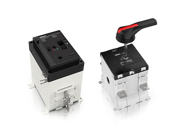
The BENY isolation equipment range includes panel-mounted and DIN-rail-mounted options. Put each proposed device tag beside its circuit duty and installation location before choosing a mounting format. The supplier's named model and connection information should then match that schedule.
Make the plan usable during a shutdown
The isolation schedule should connect each device tag to a physical location and the equipment it controls. Labels must agree with the drawing, and an authorized worker must be able to reach the operating point under the site's access arrangements. Responsibility for keys, permits and coordination between contractors also needs an owner.
Electrical isolation and verification remain work for qualified personnel using the applicable procedure. The planning document should not suggest that a displayed switch position proves the work area is de-energized. Illuminated solar modules can remain an electrical source, and the actual circuit boundaries still matter.
Test the plan against a real service visit
Before handover, walk through a representative maintenance scenario with the drawings and the responsible people. Can they identify the correct device without guessing? Does the marked boundary include the cable or component being serviced? Can the site keep unrelated equipment operating without confusing the work area?
Record unresolved points as design or documentation actions. Sometimes the result is an additional isolation point; sometimes it is better labelling, a revised access arrangement or a clearer procedure. The deliverable is a traceable means of controlling the required work area, with evidence for the chosen equipment. Counting switches is a poor substitute for that review.